Temperature Controlled Dc Fan Circuit Using Thermistor

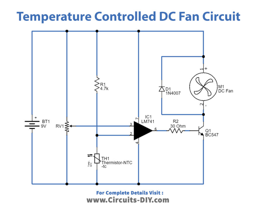
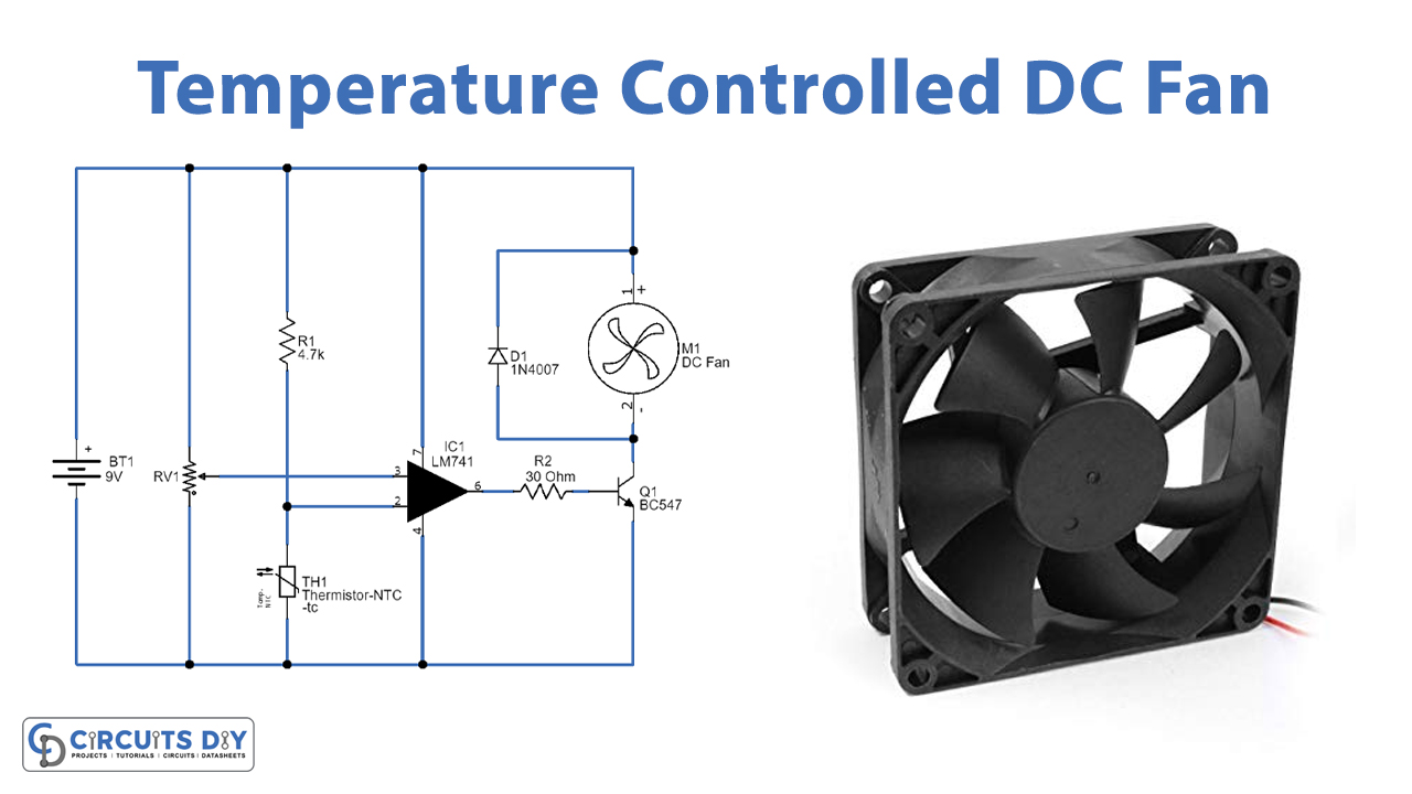
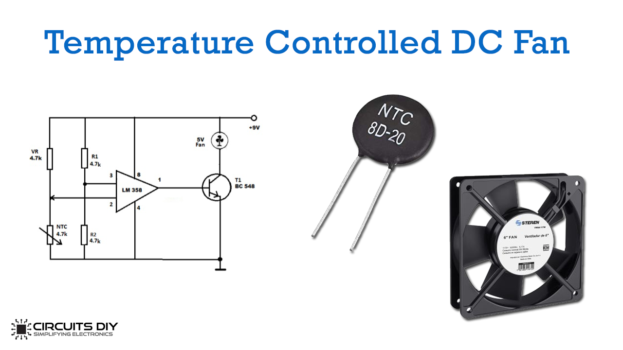
Temperature Controlled Dc Fan Circuit Using Thermistor Working of automatic temperature controlled fan using thermistor. it works on the principle of thermistor. in this circuit, pin 3 (non inverting terminal of op amp 741) is connected with the potentiometer and pin 2 (inverting terminal) is connected in between of r2 and rt1 (thermistor) which is making a voltage divider circuit. Working explanation. the basic working principle of the temperature control dc fan is based on the working of the thermistor. here, lm358 compares the voltage across the thermistor and the voltage across the resistor. at room temperature, the voltage across the thermistor will be greater than or equal to the voltage across the resistor.

Temperature Controlled Dc Fan Circuit Using Thermistor How to make a temperature controlled fan using thermistor, 12v dc & 220v ac fan. ( heat sensor fan cooling circuit )components used in this project:–1. 10k n. This tutorial will explain how to control a dc fan speed by using the temperature sensor (thermistor). when the temperature rises above the set value, the fan switches on. and stops when the temperature returns to the normal condition automatically. the temperature sensor circuit using a thermistor exploits the property of a sensor to operate. For the complete tutorial on this temperature controlled dc fan, visit the below link: circuitdigest electronic circuits temperature controlled d. 4) now solder one terminal of the brushless dc fan with the 10k thermistor & other with the collector terminal of the bd139 transistor. 5) power the circuit using a 6v voltage regulator (lm7806). 6) test the circuit by bringing it near to a heat source. circuit diagram for temperature controlled dc fan working explanation.

Temperature Controlled Dc Fan Using Thermistor For the complete tutorial on this temperature controlled dc fan, visit the below link: circuitdigest electronic circuits temperature controlled d. 4) now solder one terminal of the brushless dc fan with the 10k thermistor & other with the collector terminal of the bd139 transistor. 5) power the circuit using a 6v voltage regulator (lm7806). 6) test the circuit by bringing it near to a heat source. circuit diagram for temperature controlled dc fan working explanation. Here we are going to demonstrate a simpler version of a temperature controlled dc fan. you can control any 12 volts 1a dc fan with this circuit according to the temperature changes. to detect the temperature we have used a 10k ntc thermistor. it is a resistance thermometer, its resistance changes inverse proportionally to the temperature. Simplest 12v cooling fan controller with temperature status using thermistor temperature sensor ntc mf52 103 thermistor, nec d882 (tp 120) and tl431 transist.

Comments are closed.