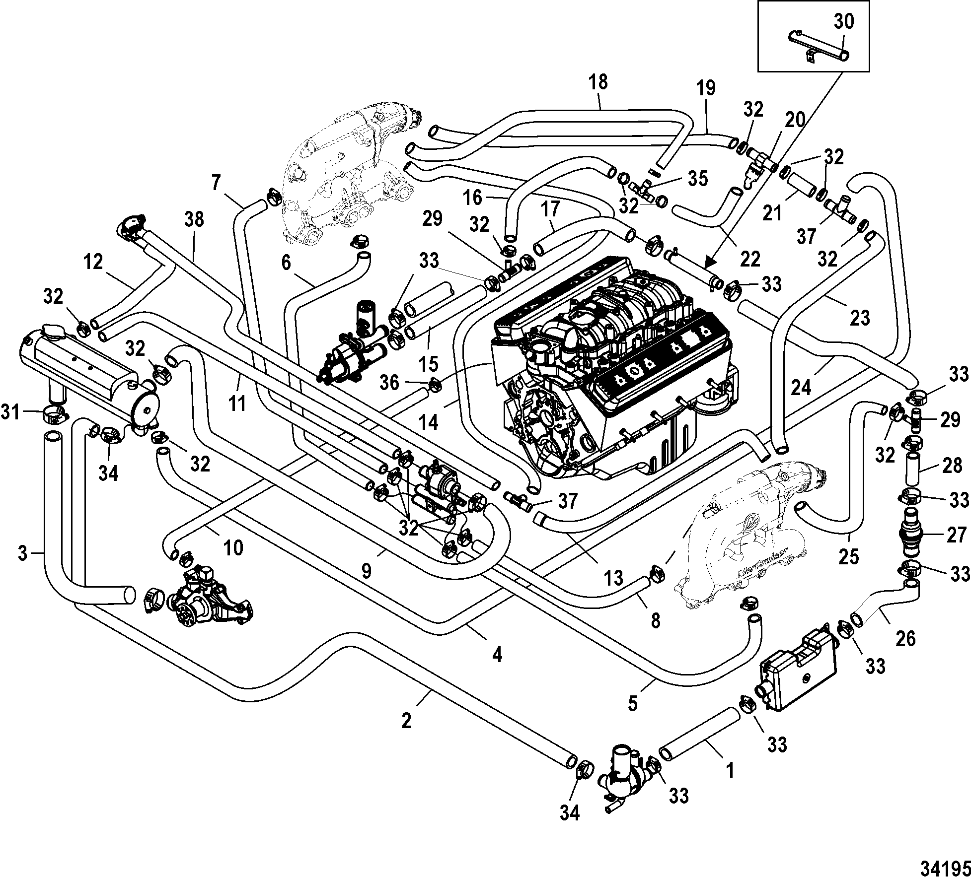
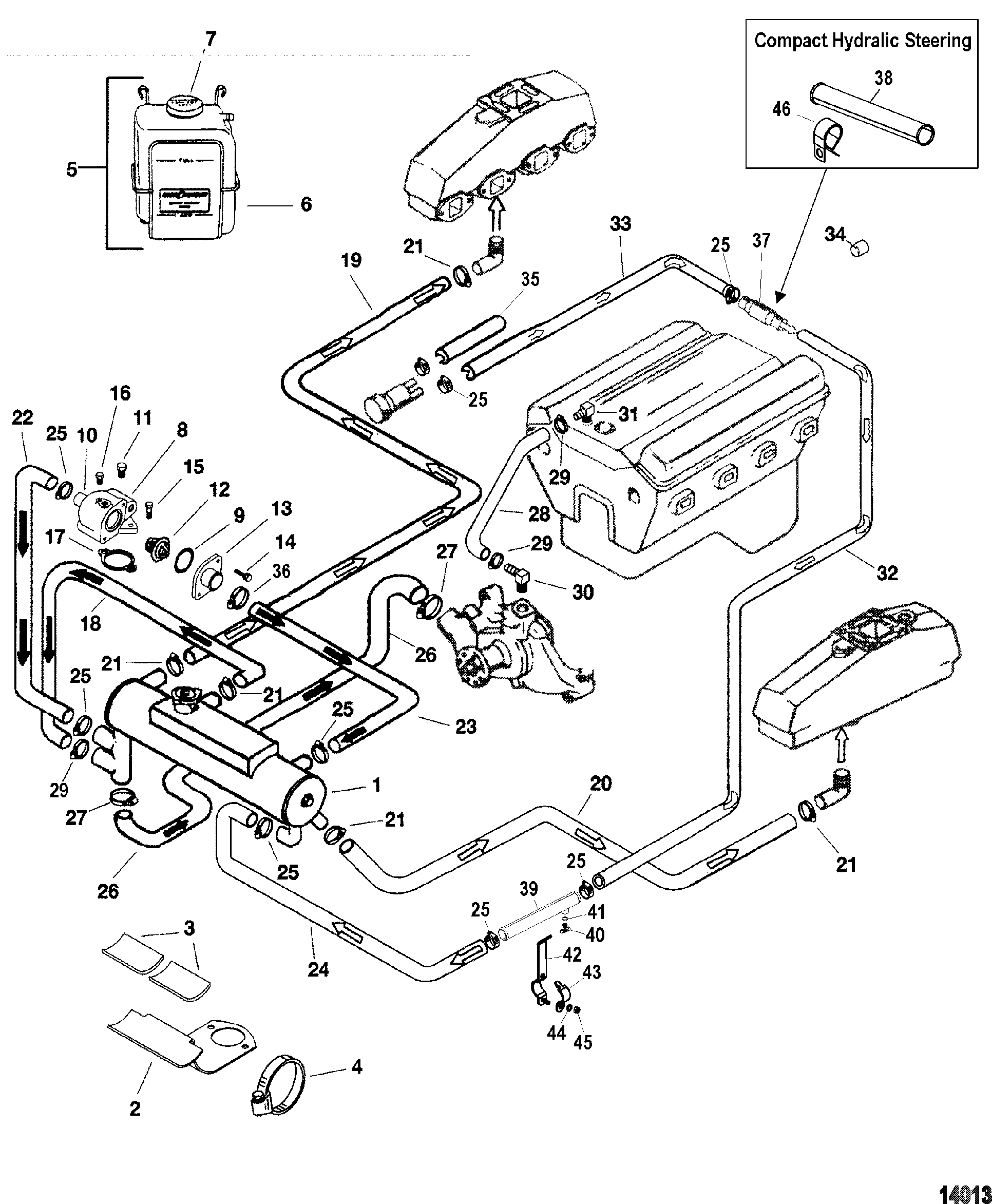
Mercruiser 5 7 Cooling Diagram

Mercruiser 5 7 Cooling System Diagram A mercruiser 5.7 water flow diagram is a visual representation of how water flows through the mercruiser 5.7 engine’s cooling system. this diagram outlines the different components and pathways that the water takes to ensure the engine stays at a proper operating temperature. understanding this diagram is essential for troubleshooting cooling. The cooling system diagram of a 5.7 mercruiser engine showcases a complex network of components working together to regulate temperatures and prevent engine damage. at the heart of this system is the water pump, responsible for circulating coolant throughout the engine. this circulating coolant absorbs heat generated by the engine and carries.

Mercruiser 5 7 Cooling System Diagram Sepidehching Parts for mercruiser 5.7l gm 350 v 8 1988 1995 standard cooling system (design ii) revise search: all models > 5.7l gm 350 v 8 1988 1995 > 0b525982 0f600999 > standard cooling system (design ii). View online or download mercury mercruiser alpha 5.7l instruction manual, manual, installation manual draining the cooling system. 160. wiring diagrams. 126. Rine power part.this manual also contains many commonly used parts for the 350 cid pr. vortec en gine. most parts fit both the 5.7l vortec and th. 350 cid engine.as a reference, marine power utilizes 5.7v when referring to the vortec engine and 350 when referring to the p. Understanding the 5.7 mercruiser water flow diagram. the 5.7 mercruiser water flow diagram is an essential tool for understanding how the cooling system of the engine works. it provides a visual representation of the path that water takes throughout the system, ensuring that the engine remains at an optimal operating temperature.

Comments are closed.