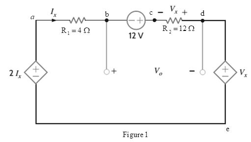
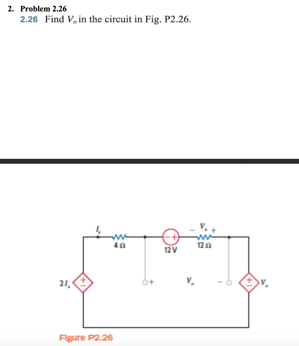
Find V O In The Circuit In Fig P2 26 Bartleby

Find V O In The Circuit In Fig P2 26 Bartleby Ch. 2 find vo in the network in fig. p2.28. ch. 2 find v1,v2, and v3 in the network in fig. p2.29. ch. 2 if vo=3v in the circuit in fig. p2.30, find vs. ch. 2 find the power supplied by each source in the ch. 2 the 10 v source absorbs 2.5 mw of power. A voltmeter having a f.s.d. of 100v and a sensitivity of 1.6 kohm v is used to measure voltage v1 in the circuit of given figure. determine the value of voltage v1 with the voltmeter not connected, and the voltage indicated by the voltmeter when connected between a and b Α 40 ΚΩ Β 60 ΚΩ v₁ 100 v.

Find V O And I O In The Circuit Of Fig 2 26 Figure 2 26 For Practice Prob 2 7 Bartleby B) find the power dissipated in each resistor. c) findvg. d) show that the power delivered by the current source is equal to the power absorbed by all the other elements. for the fig2.24 find (a) r and (b) the power supplied by the 250v source. q2: find the theuenin equivalent circuit for the network shown in fig. 2.126 for an amplifier having a slew rate of 40 v µs, what is the highest frequency at which a 2 v 2.125 an inverting amplifier with a gain of −5 v v and input resistance 20 kΩ uses an op amp with 2.124 for operation with 10 v output pulses with the requirement that the sum of the rise and fall times represent. This is definitely a good start. the "mistake" is that the terminal vo didn't collapse to the top of the equivalent resistance, it is buried inside that 20 kohm resistance. . the final part of the solution is "unraveling" the lumped resistor now that you can identify all of the parameters of that one resistance (voltage, current, resistanc. Find v o in the circuit in fig. p2.54. 02:06. find v o in the circuit in fig. p4.34. 01:48. find v o in the circuit in fig. p4.35. 02:42. find v o in the circuit in fig. p2.116. view more. video solution, solved step by step from our expert human educators: find v o in the circuit in fig. p2.26.

Solved Find V 0 In The Circuit In Fig P2 26 Chegg This is definitely a good start. the "mistake" is that the terminal vo didn't collapse to the top of the equivalent resistance, it is buried inside that 20 kohm resistance. . the final part of the solution is "unraveling" the lumped resistor now that you can identify all of the parameters of that one resistance (voltage, current, resistanc. Find v o in the circuit in fig. p2.54. 02:06. find v o in the circuit in fig. p4.34. 01:48. find v o in the circuit in fig. p4.35. 02:42. find v o in the circuit in fig. p2.116. view more. video solution, solved step by step from our expert human educators: find v o in the circuit in fig. p2.26. For the amplifier in fig. p4.15, find the gain (r1=3.5 kq, r2=27 kq) 2 vs r₂ r₁ ov. problem 4.17: you have access to resistors with values 1 k2, 1.5 kn, and 5.0 k2. you have a voltage signal from a transducer with a maximum voltage of 0.2 v. using a noninverting op amp configuration, what maximum output voltages could you provide with the. Find v, in the circuit in fig. p5.32 using thévenin's theorem. 12 v 4 kn 2 kn 12 kn vo ()4 ma 2 k2 arrow forward mechatronixone is a manufacturer of an industrial and toy robots.

Solved Find V O In The Network In Fig P2 26 Fig P2 26 Find V O In The 1 Answer For the amplifier in fig. p4.15, find the gain (r1=3.5 kq, r2=27 kq) 2 vs r₂ r₁ ov. problem 4.17: you have access to resistors with values 1 k2, 1.5 kn, and 5.0 k2. you have a voltage signal from a transducer with a maximum voltage of 0.2 v. using a noninverting op amp configuration, what maximum output voltages could you provide with the. Find v, in the circuit in fig. p5.32 using thévenin's theorem. 12 v 4 kn 2 kn 12 kn vo ()4 ma 2 k2 arrow forward mechatronixone is a manufacturer of an industrial and toy robots.

Comments are closed.