Cooling Fan Controller Circuit Diagram

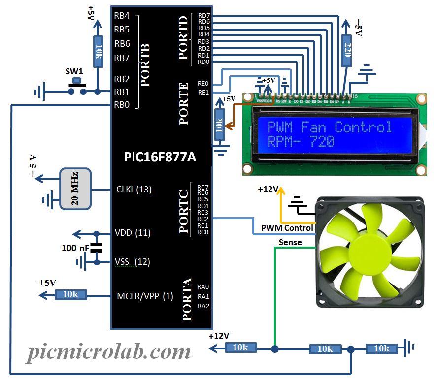
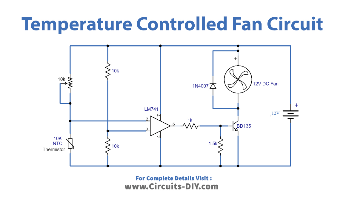
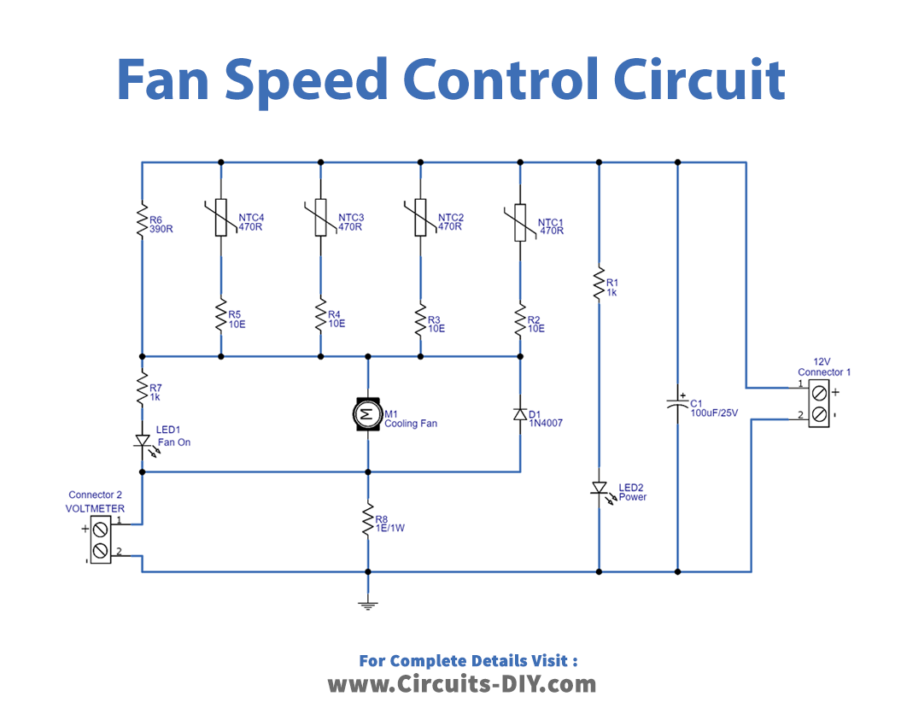
Automatic Cooling Fan Controller Circuit Diagram A fan controller schematic refers to the circuit diagram or design of a fan controller. it outlines the components and connections required to build the fan controller. this schematic can be used by electronics enthusiasts and professionals to build their own fan controllers or to understand the internal workings of existing controllers. Fan control circuits range from simple switches that boost the fan speed at a certain temperature, to digitally controlled fans with continuously variable speed. high speed low speed switches are inexpensive, but the sound of sudden speed changes can be annoying. digitally controlled fans perform well, but those circuits are more costly, and.

Cooling Fan Control Circuit At Jack Herrera Blog Figure 2 shows the differences between 3 wire and 4 wire fan circuits. figure 2. 3 and 4 wire fans. fan control. no control: the simplest method of fan control is not to use any at all; just run a fan of appropriate capacity at full speed 100% of the time. the main advantages of this are guaranteed fail safe cooling and a very simple external. Cooling fan speed control circuits play a crucial role in maintaining an optimal operating temperature for electronic devices. by adjusting the fan speed based on the temperature, these circuits ensure efficient heat dissipation without unnecessary noise or power consumption. this circuit is designed to control small cooling fan (any size that. These two types of speed control circuits are found in the table below. integrated fan controller. discrete fan controller. 2 wire. an external fet is used to drive the fan. speed control can only be implemented with power measurement. fan driven with adjustable pwm signal and external fets. speed control can only be implemented with power. If dc fan is powered by 12v 5v pwm signal, the fan's speed can be controlled. in this tutorial, we are going to learn how to turn on off a fan using arduino. controlling the fan's speed will be presented in another tutorial. to turn on off a fan, we need to use a relay in between arduino and fan. arduino can turn on off the fan via the relay.

Cooling Fan Speed Control Circuit These two types of speed control circuits are found in the table below. integrated fan controller. discrete fan controller. 2 wire. an external fet is used to drive the fan. speed control can only be implemented with power measurement. fan driven with adjustable pwm signal and external fets. speed control can only be implemented with power. If dc fan is powered by 12v 5v pwm signal, the fan's speed can be controlled. in this tutorial, we are going to learn how to turn on off a fan using arduino. controlling the fan's speed will be presented in another tutorial. to turn on off a fan, we need to use a relay in between arduino and fan. arduino can turn on off the fan via the relay. With dual cooling fans, there are two methods for wiring up the relay kit. this is based on the draw from the fans, if the fans are larger and draw more than 15 amps each, it's recommended to install a second relay kit as shown below. for smaller fans, both fans can be connected to a single relay as shown above, and the proper fuse should be. 30: constant 12v, unswitched 85: signal (switched 12v) 86: ground (completes circuit) 87: consumer (fan) 12v 87b: extra consumer (same as 87) 12v switched wire. may be green wire at a c clutch. note: or in an ’84 to ‘89 240 you may use the a c power ‘on’ wire: red white wire at ac switch microswitch in dash.

Schematic Diagram Of An Electric Fan Circuit Diagram With dual cooling fans, there are two methods for wiring up the relay kit. this is based on the draw from the fans, if the fans are larger and draw more than 15 amps each, it's recommended to install a second relay kit as shown below. for smaller fans, both fans can be connected to a single relay as shown above, and the proper fuse should be. 30: constant 12v, unswitched 85: signal (switched 12v) 86: ground (completes circuit) 87: consumer (fan) 12v 87b: extra consumer (same as 87) 12v switched wire. may be green wire at a c clutch. note: or in an ’84 to ‘89 240 you may use the a c power ‘on’ wire: red white wire at ac switch microswitch in dash.

Comments are closed.