Basics Of Solidworks Reference Geometry Planes Basics Of Solidworks Reference Geometry Planes

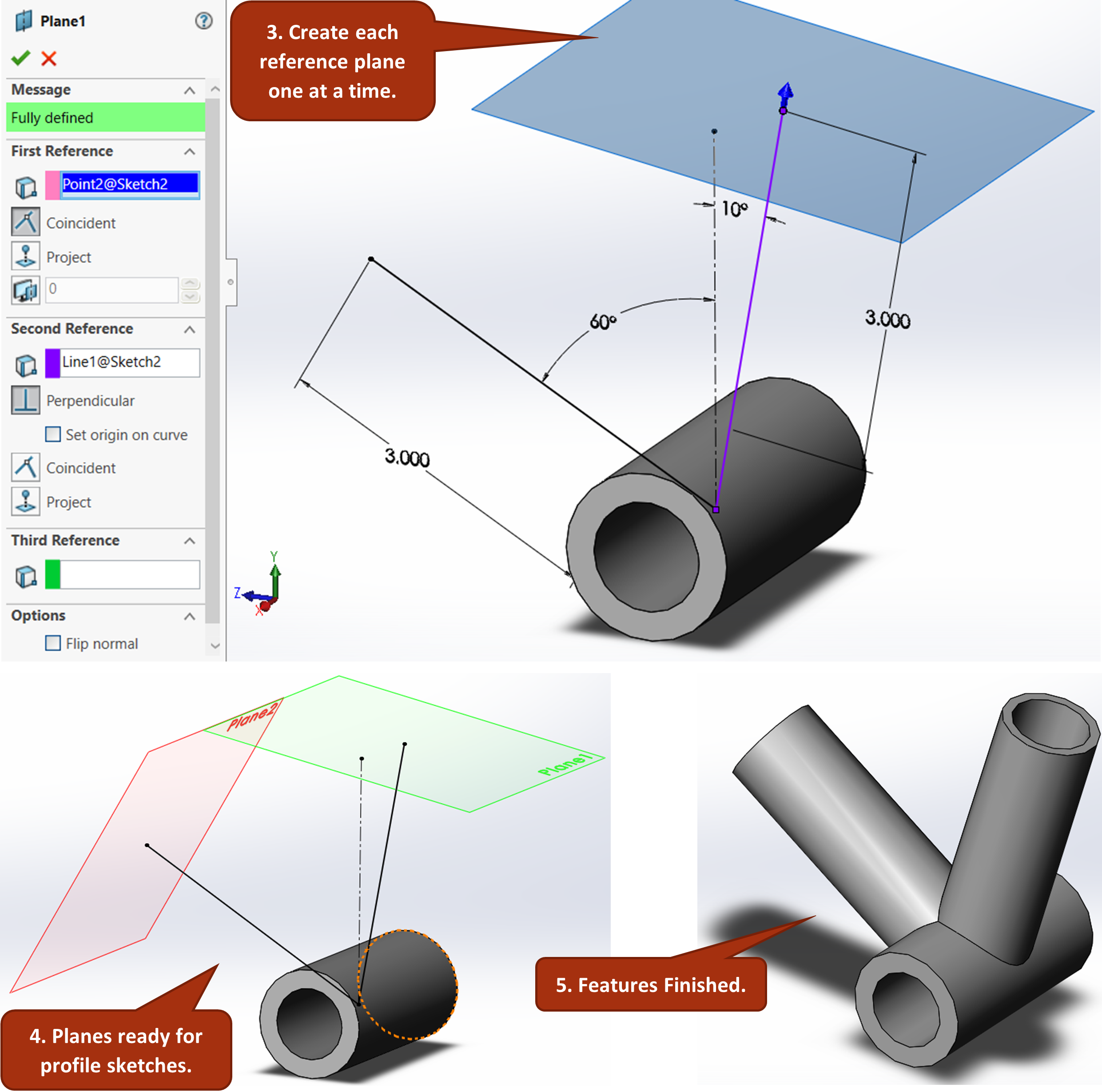
Reference Geometry Planes Introduction To Solidworks Part 1 For basic solidworks models, users can often complete designs by leveraging only the default planes and available model geometry. however, as the complexity of designs increases, it often becomes necessary to create and utilize reference geometry to produce models with appropriate design intent. reference geometry includes planes, axes. The most common type of reference plane is an offset plane. to create an offset plane, select the reference geometry drop down on the commandmanager and choose the plane option. once the option to create a plane is open, select a face or another plane and set a distance for the offset. (figure 1 & 2) there is also the option to create multiple.

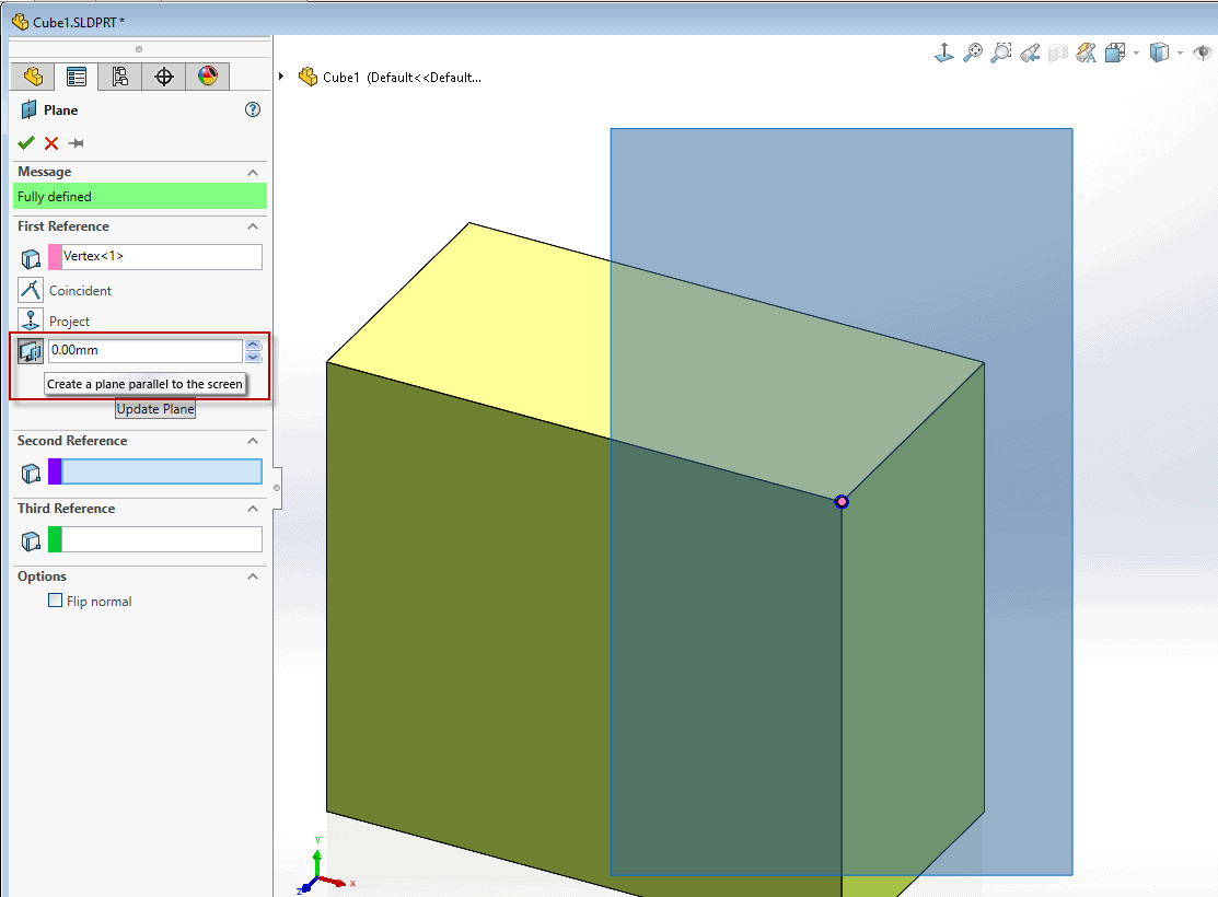
How To Create Reference Planes In Solidworks Youtube Reference geometry. reference geometry defines the shape or form of a surface or a solid. reference geometry includes items such as planes, axes, coordinate systems, and points. you can use reference geometry in the creation of several kinds of features. for example:. Utilizing solidworks reference geometry for complex designs. for basic solidworks models, users can often complete designs by leveraging only the default planes and available model geometry. however, as the complexity of designs increases, it often becomes necessary to create and utilize reference geometry to produce models with appropriate. You can create planes in part or assembly documents. you can use planes to sketch, to create a section view of a model, for a neutral plane in a draft feature, and so on. you select geometry and apply constraints to the geometry to define reference planes. you can create a reference plane that is parallel to the screen without using the plane. The types of reference geometry that exist are planes, axes, coordinate systems, and points. we will save axes, coordinate systems, and points for you to learn on a case by case basis when you get more familiar with solidworks. reference planes are certainly the most commonly used reference geometry (besides reference sketches).

Basics Of Solidworks Reference Geometry Planes Basics Of Solidworks Reference Geometry Planes You can create planes in part or assembly documents. you can use planes to sketch, to create a section view of a model, for a neutral plane in a draft feature, and so on. you select geometry and apply constraints to the geometry to define reference planes. you can create a reference plane that is parallel to the screen without using the plane. The types of reference geometry that exist are planes, axes, coordinate systems, and points. we will save axes, coordinate systems, and points for you to learn on a case by case basis when you get more familiar with solidworks. reference planes are certainly the most commonly used reference geometry (besides reference sketches). You can use planes to sketch, to create a section view of a model, for a neutral plane in a draft feature, and so on. click plane (reference geometry toolbar) or insert > reference geometry > plane . in the propertymanager, select an entity for first reference . the software creates the most likely plane based on the entity you select. Online help. reference geometry defines the shape or form of a surface or a solid. reference geometry includes items such as planes, axes, coordinate systems, and points. you can use reference geometry in the creation of several kinds of features. for example: planes are used in lofts and sweeps. an axis is used in a circular pattern.

Comments are closed.