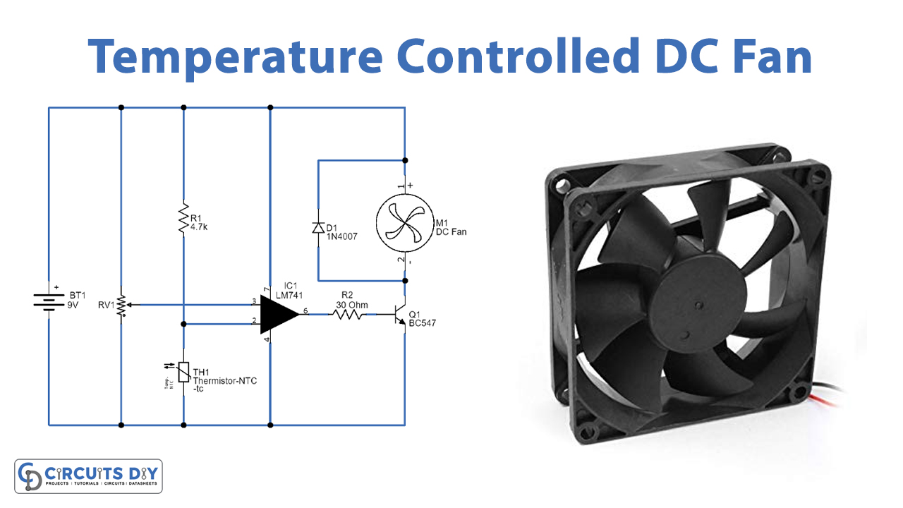
Automatic Fan Controller Circuit Diagram Using Temperature Sensor Circuit Diagram Electrical

Temperature Controlled Fan Using Lm741 Ic Working of automatic temperature controlled fan using thermistor. it works on the principle of thermistor. in this circuit, pin 3 (non inverting terminal of op amp 741) is connected with the potentiometer and pin 2 (inverting terminal) is connected in between of r2 and rt1 (thermistor) which is making a voltage divider circuit. The threshold level of the automatic fan controller is made with a thermometer. place the sensor on the surface which temperature you want to monitor. read the temperature with the thermometer and adjust the threshold level of the fan with p1 at the desired temperature. the second comparator goes from low to high state when the threshold level.

Automatic Fan Controller Circuit Diagram Using Temperature Sensor Circuit Diagram Electrical Automatic temperature controlled fan project using arduino. in this arduino based project, we are going to build a temperature controlled fan using arduino. with this circuit, we will be able to adjust the fan speed in our home or office according to the room temperature and also show the temperature and fan speed changes on a 16x2 lcd display. The fan and the plug were later added using photoshop. the diagram consists of an arduino,a relay, an lm35 sensor, an ac fan, and a plug. the temperature controlled fan circuit is very simple. the lm35 sensor has 3 pins vcc, gnd and analog output pin. the vcc pin will be connected to the 5v pin of arduino. Automatic fan controller using temperature sensor circuit diagramused this component:ic ca3140 1 pcs12v dc fan 1 pcs2n2222 transistor 1 pcs1n4007 pn juncti. Circuit diagram of the temperature based fan speed control & monitoring with arduino & lm35 is shown above. arduino is at the heart of the circuit as it controls all functions. lm35 is a precision integrated circuit whose output voltage is linearly proportional to celsius (centigrade) temperature. it is rated to operate over a 55°c to 150°c.

Automatic Fan Controller Circuit Diagram Using Temperature Sensor Youtube Automatic fan controller using temperature sensor circuit diagramused this component:ic ca3140 1 pcs12v dc fan 1 pcs2n2222 transistor 1 pcs1n4007 pn juncti. Circuit diagram of the temperature based fan speed control & monitoring with arduino & lm35 is shown above. arduino is at the heart of the circuit as it controls all functions. lm35 is a precision integrated circuit whose output voltage is linearly proportional to celsius (centigrade) temperature. it is rated to operate over a 55°c to 150°c. Second design. the second temperature controlled dc fan circuit project discussed below automatically senses the ambient temperature and adjusts the fan motor speed to keep the surrounding temperature under control. this automatic processing is done through an arduino and a temperature sensor ic lm35. by: ankit negi. May 5, 2017. here is a circuit through which the speed of a fan can be linearly controlled automatically, depending on the room temperature. this temperature controlled fan circuit is highly efficient as it uses thyristors for power control. alternatively, the same circuit can be used for automatic temperature controlled ac power control.

Temperature Controlled Dc Fan Circuit Using Thermistor Second design. the second temperature controlled dc fan circuit project discussed below automatically senses the ambient temperature and adjusts the fan motor speed to keep the surrounding temperature under control. this automatic processing is done through an arduino and a temperature sensor ic lm35. by: ankit negi. May 5, 2017. here is a circuit through which the speed of a fan can be linearly controlled automatically, depending on the room temperature. this temperature controlled fan circuit is highly efficient as it uses thyristors for power control. alternatively, the same circuit can be used for automatic temperature controlled ac power control.

Automatic Fan Controller Circuit Diagram Using Temperature Sensor Electrical And Electronics

Comments are closed.